1
Electronics
2230 readers
1 users here now
Projects, pictures, industry discussions and news about electronic engineering & component-level electronic circuits.
Rules
1: Be nice.
2: Be on-topic (eg: Electronic, not electrical).
3: No commercial stuff, buying, selling or valuations.
4: No circuit design or repair, tools or component questions.
5: No excessively promoting your own sites, social media, videos etc.
Ask questions in https://discuss.tchncs.de/c/askelectronics
founded 2 years ago
MODERATORS
2
der8auer got the original 5090 card from the reddit melting cable post, then demonstrated that two of the six 12V power connector cables are having 20ish amps running through them and overheating, while the other 4 cables are not.

3
24
Maker builds cool Raspberry Pi Home dashboard with an old touchscreen monitor
(www.tomshardware.com)
4
5
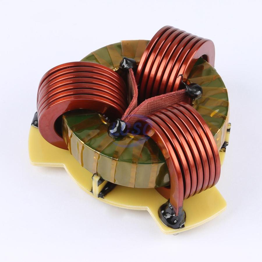
The thickness of the board beneath it gives deceptive scale. It's about 50mm tall and the toroid is 85mm in diameter.
https://www.lcsc.com/datasheet/lcsc_datasheet_2408061709_Ruishen-RSCM11548-5mH-3P_C37634003.pdf
I was looking for much smaller CMCs. Also the datasheet for this part doesn't have impedance-versus-frequency graphs so I refuse to buy it anyway :P

7
8
9
10
11
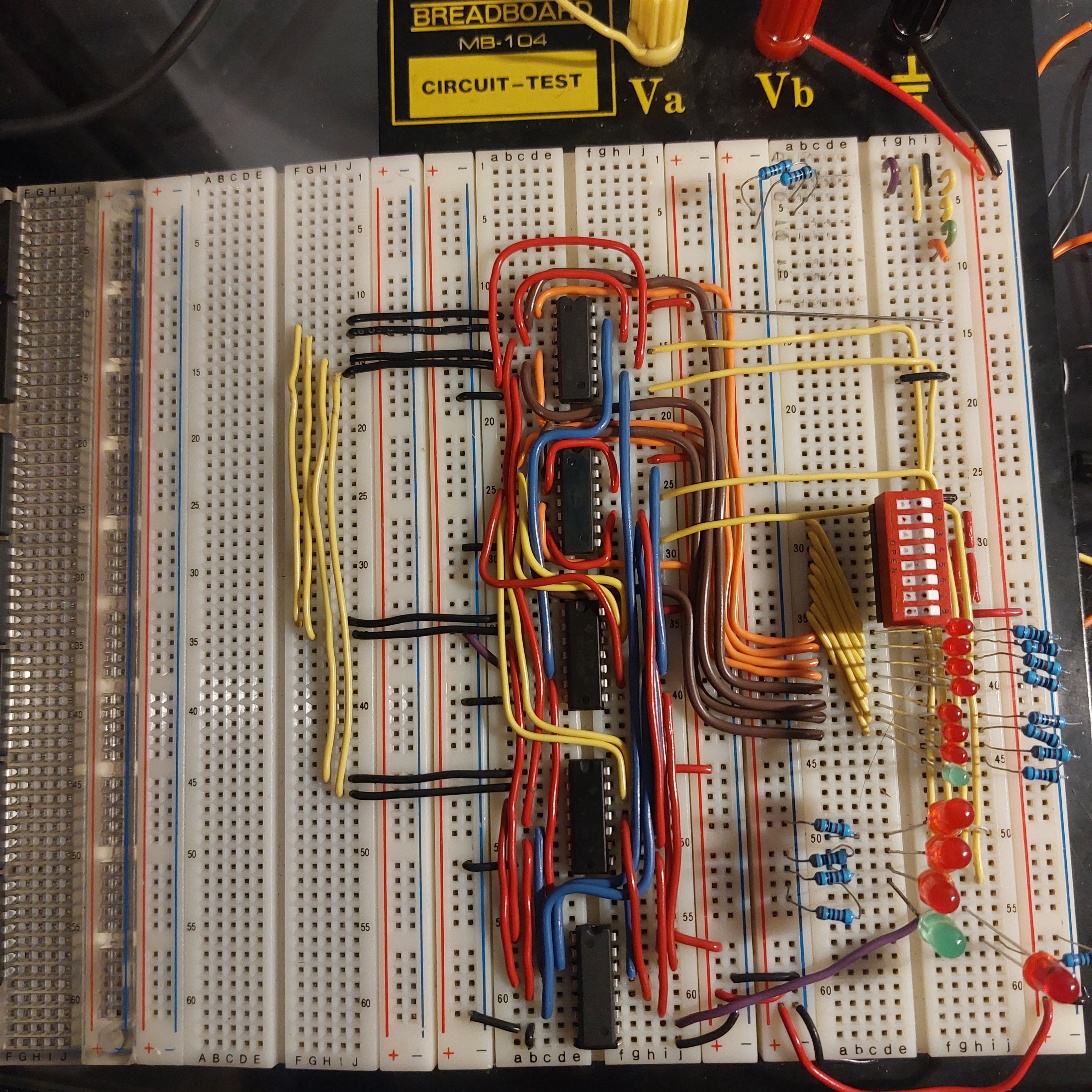
4 bit adder. Took me a few evenings this week to put together. Im quite happy that it worked first try without any bugs. Constructive criticism is encouraged.
12
13
14
15
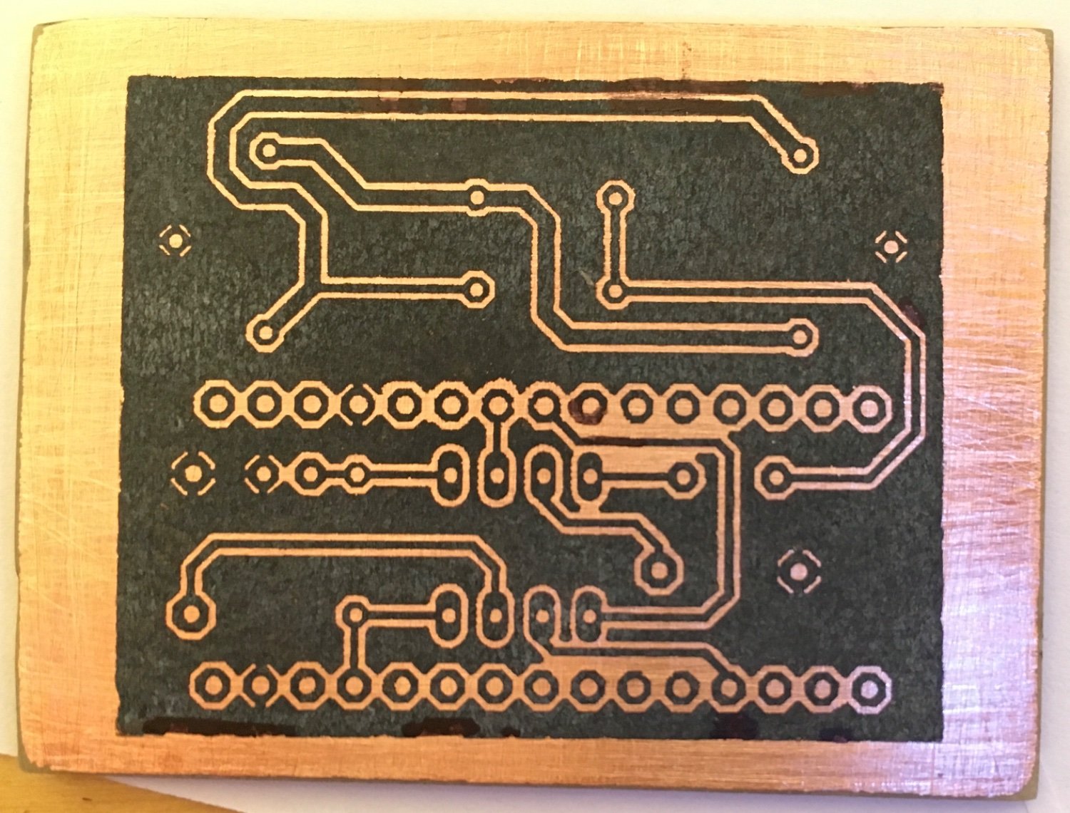
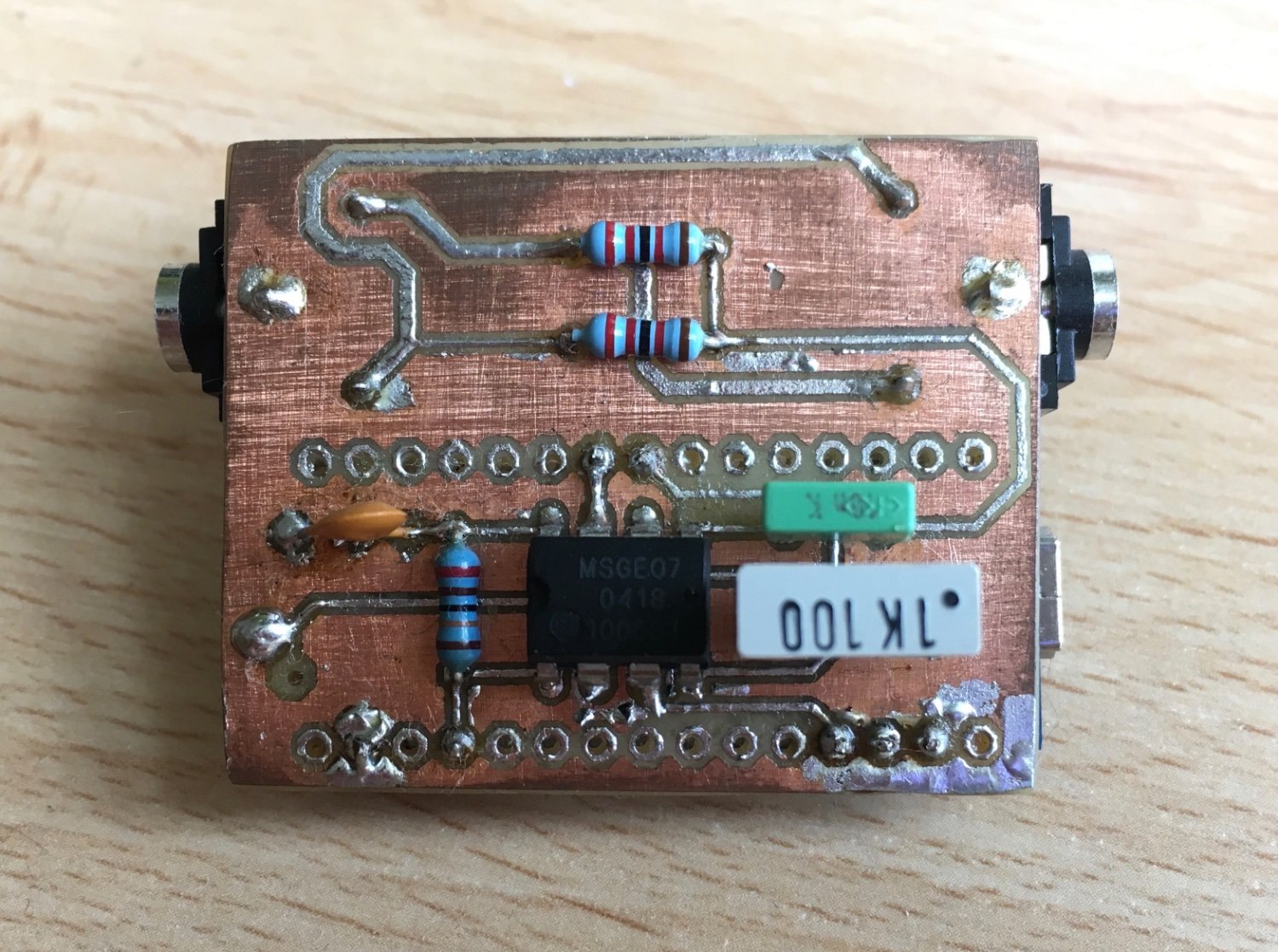
This was my first try developing my own pcb with the toner transfer method. I did this project many years back but it works perfectly to this day.
It filters an audio signal and drives led strips so they pulsate to the beat of a song.
16
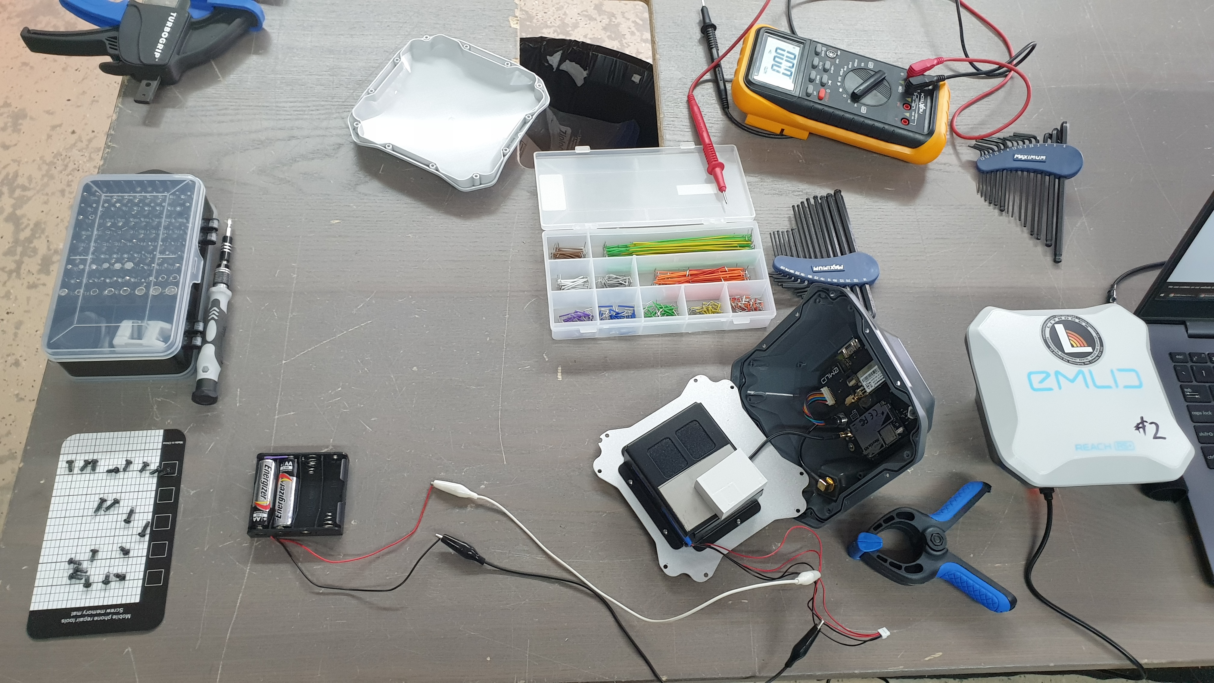
We maintain a small fleet of RTK GPS systems (Emlid Reach RS+ units or similar). But sometimes they sit too long on the shelf and parasitic drain kicks in. The manufacturer recommends recharging every three months, but ooops, this one went too long. If the batteries are too low, the battery management system (BMS) won't charge the batteries at all when you attach the USB charger cable. In this case, the batteries were testing at 0.9V rather than the desired 3.4V.
Solution: open the device, expose a tiny bit of conductor on the battery harness, and attach 3V worth of alkaline batteries for a short period. Once the lithium batteries are up a little, you can then charge with the normal USB charger again.
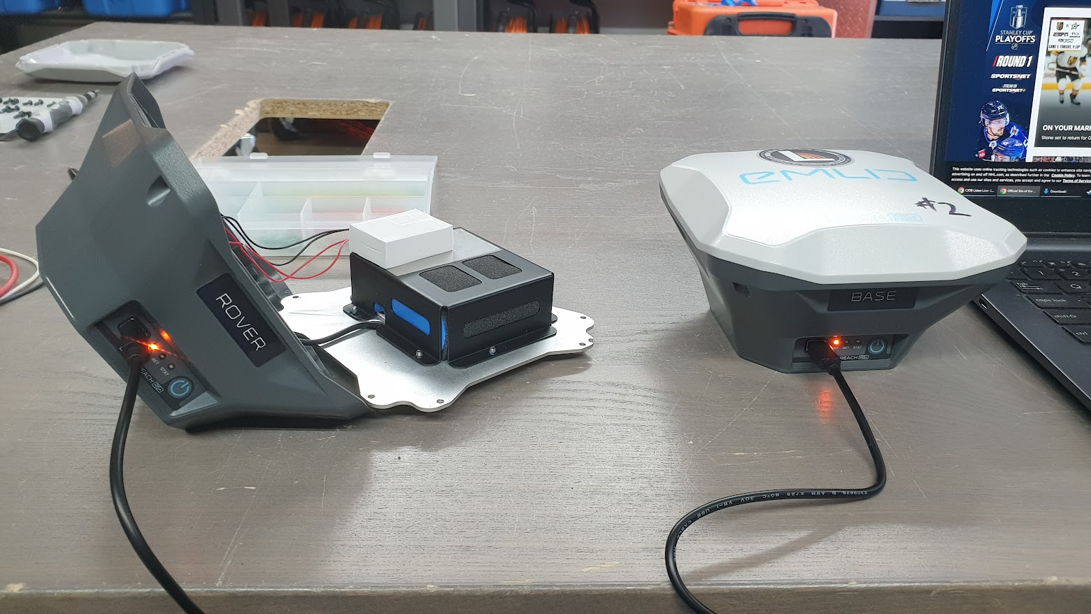
The manufacturer does not recommend opening the sealed unit, as it voids the IP67 rating. And this is not a best practice. But it works. The above photos were taken in April and the unit has been trucking along ever since. Saved a few thousand dollars :)
17
Instrument is a Geonics EM16 VLF receiver, using in the mineral exploration industry to find buried linear conductors.

19
20
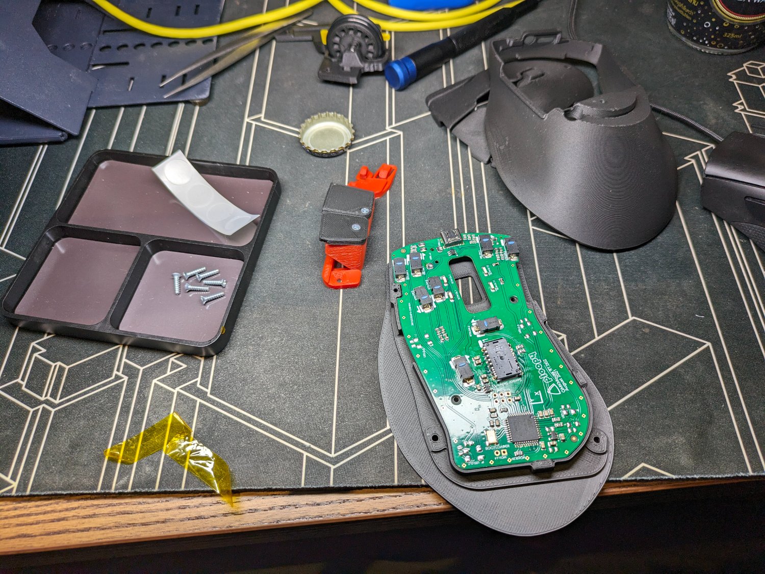
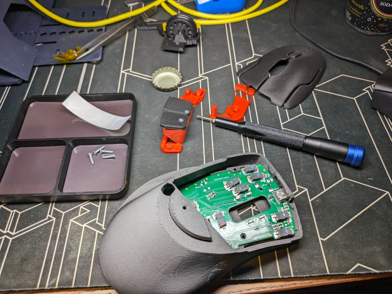
Built out my ploopy mouse today, it's been sitting on my shelf for a while. I got the self-assembly kit, had to solder on one through hole component.
So far I'm enjoying the mouse, the right mouse button is a little sticky, but I'm sure with a little readjustment it'll fall into place.
Every part of this mouse is open source, the hardware files, the PCB, the schematic, the firmware which is QMK. There's a lot to love here.
I've been playing some video games, and so far I enjoy the mouse quite a bit.
If I do have one complaint it would be the central scroll wheel doesn't have a detent, but that might just take some getting used to
I would love to see a kinesis style pinch mouse like the DXT2.
@pronk@mastodon.social @PKL@mastodon.social Great device, thank you for making it open source.


Note: I ordered their USB cables, just for solidarity, and assuming they found a cable that was very effective for a mouse, the cables I received were very strong, too stiff really to be used for a mouse cable. Luckily I had some very flexible braided USB cables already. So if you're going to order from them do not order the USB cable
22
I'm nowhereman from Belgium. Thanks for accepting me! Just started with electronics. Messing around a bit with motherboards. My 'new' secondhand motherboard got hit by the ground a think whilst in transport. And when I plugged it in some chips burned. The board didn't look like it would do that. Only the corner was hit so I thought it would be fine. I was wrong. But, because of that I wanted to learn about what went wrong.

23
24
This decade old electric cooler box gave up the ghost around 2 years ago, with the indoor outlet plug no longer working. The independent 12v input was still operational, so I kept it with the intention of eventually fixing it...
And two years later, this is the eventually 😅. The integrated 10v ~45w unit had failed short on the primary side, with a burnt out Y-capacitor and some fried zeners. I started removing bits from the board to try and find all the broken components... but ended up letting out the magic smoke in the process, oops!
I set out looking for a new power supply, and came across a 12v 45w unit from Meanwell. It was actually smaller than the cooler's original power supply too, meaning more internal space to use later 🤫
Spoiler
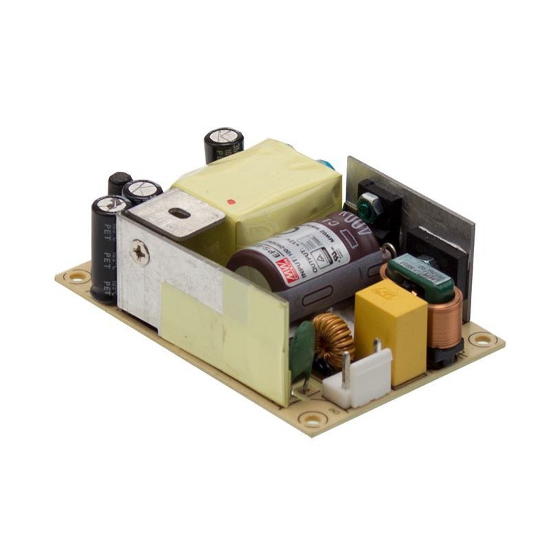
After searching for a distributor that was actually willing to ship it to a home address, I ordered, and boom:
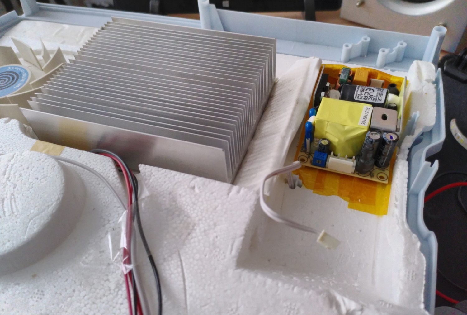
It's so tiny compared to the original.
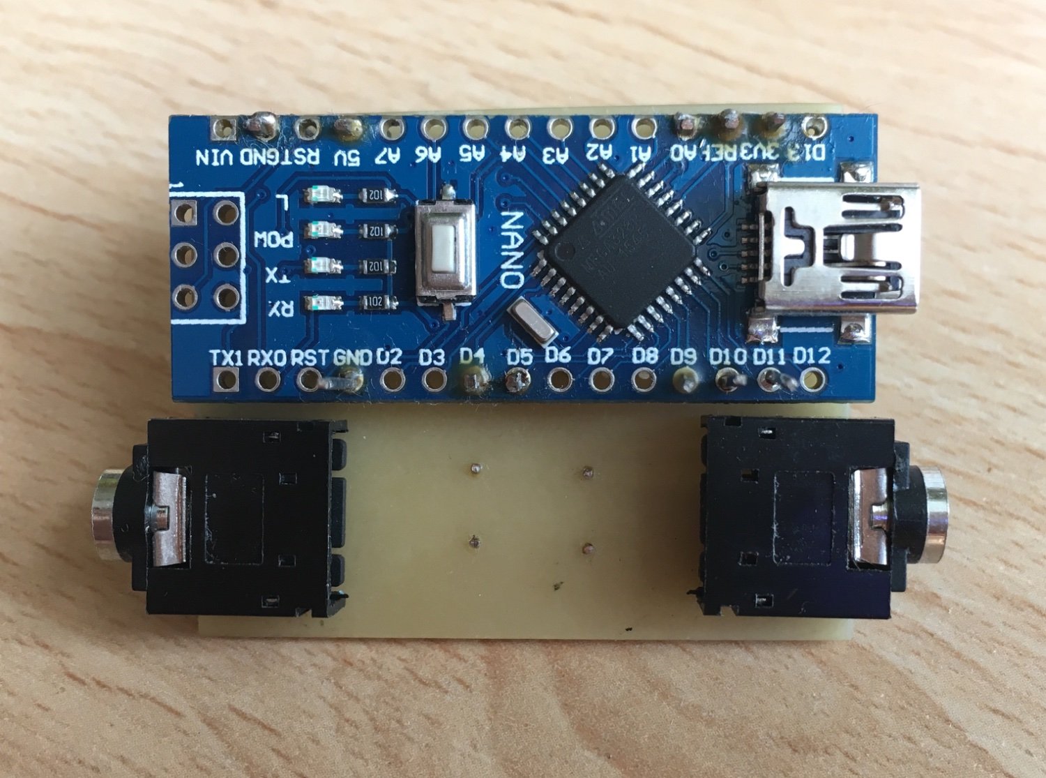
Next I installed an Arduino Nano to control the TEC/peltier module & fan via a cheap LED repeater. I was hoping to reuse the internal temperature sensors, but left them disconnected for now
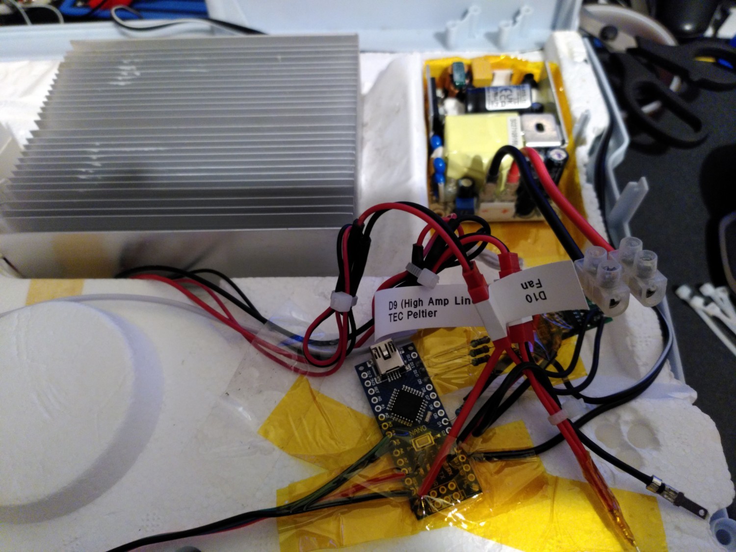
After hours writing the arduino code, I finally got it into a usable state. There were issues with brownouts rebooting the Arduino, however with the Meanwell supply in-circuit those mysteriously stopped.
There are 3 power modes now for the module: 30W, 40W and 50W - with the first two using PWM, and the last one giving it all the beans. I wanted to PWM control the fan too, but decided against it since it sounded absolutely terrible at whatever PWM frequency the Nano is using.
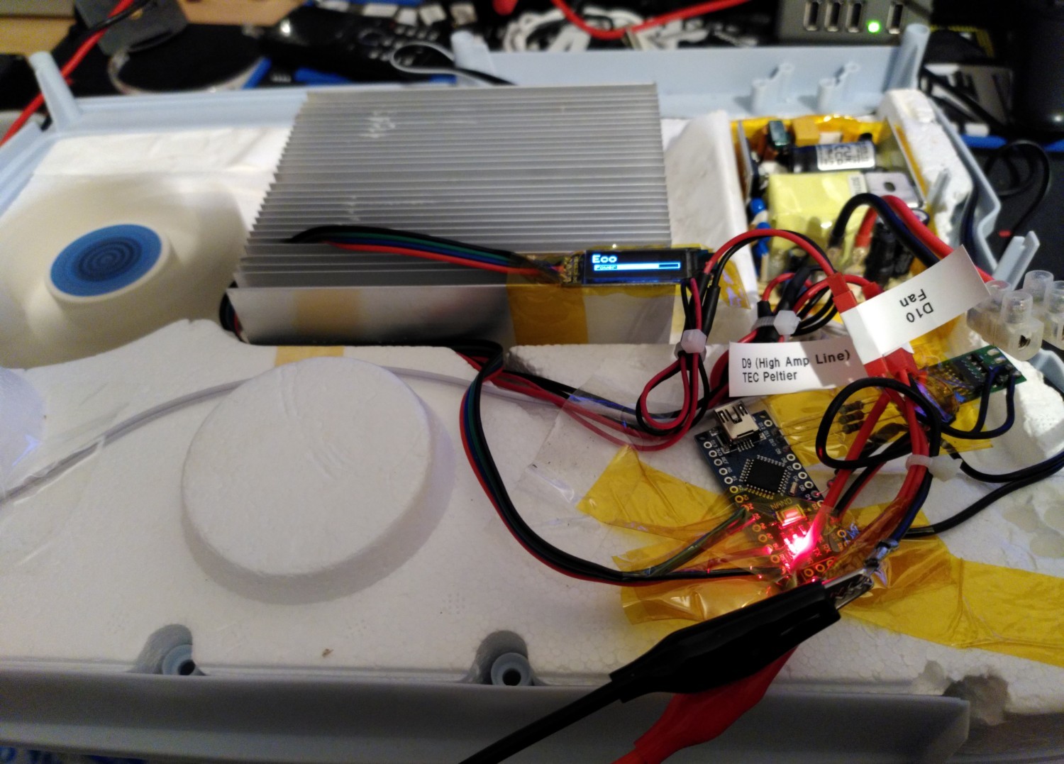
It powers on to 40W by default, which is under the 45W max rating of the PSU.
Everything looks good so far running from the bench supply:
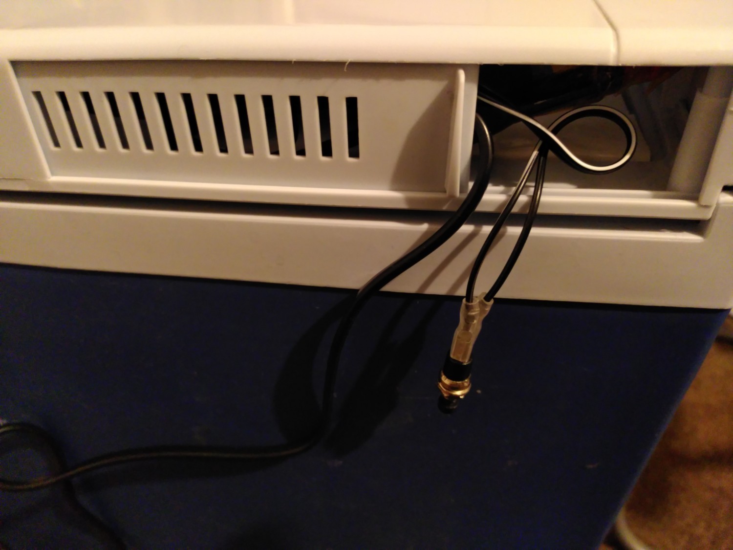
Now all that was left was to connect the internal supply, and the 12v vehicle input. I was actually supposed to use JST connectors for the Meanwell psu, but didn't have anything on hand - so improvised with crimping spade terminals and friction fitting those on
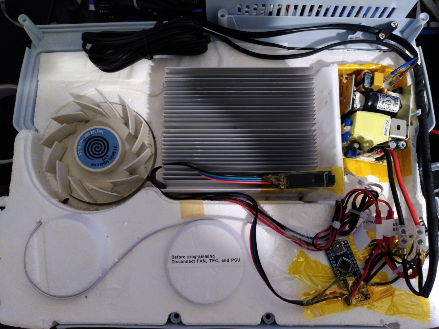
And the moment of truth. Up until this point I hadn't actually checked if the replacement psu was working or not
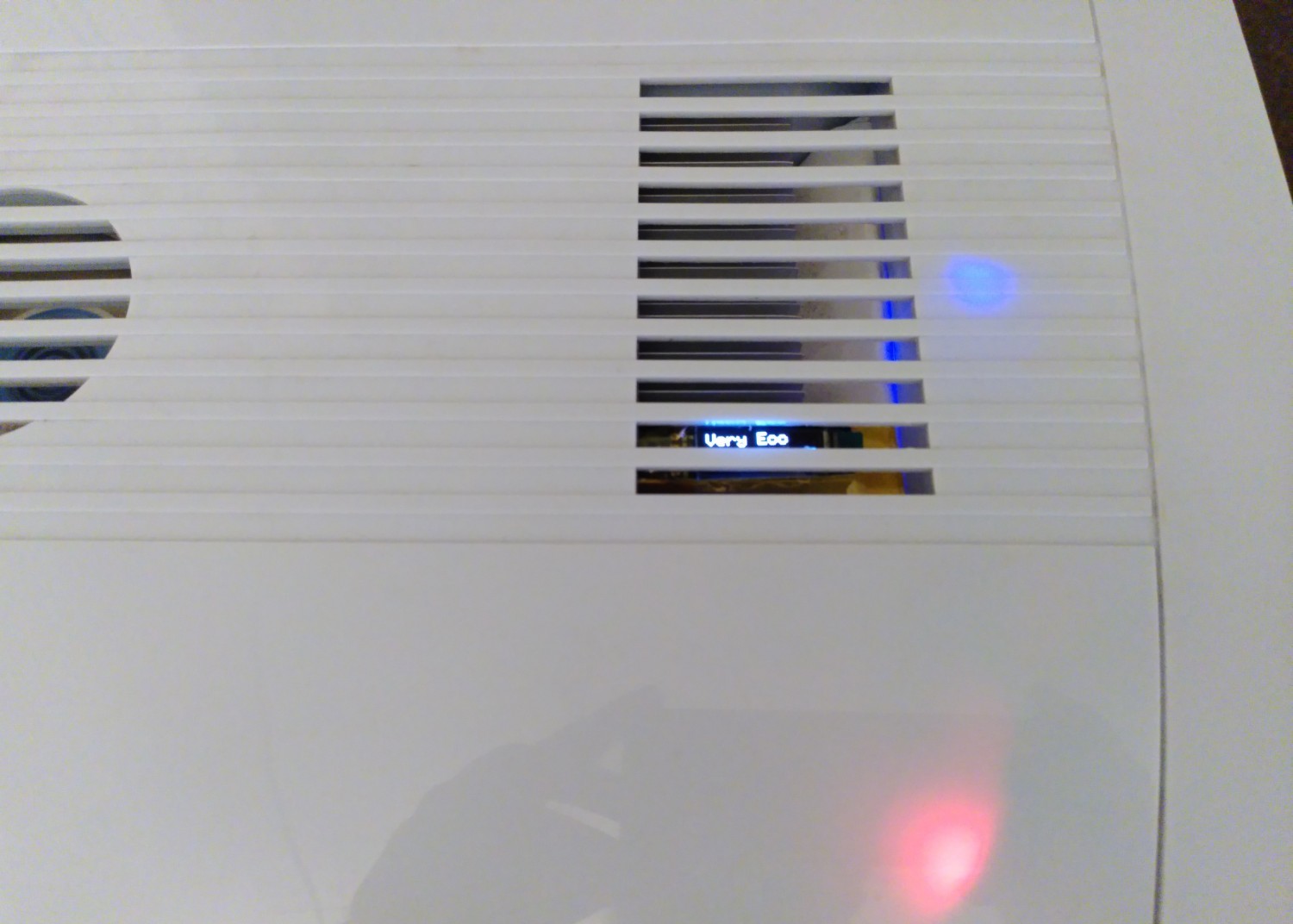
Looking good! I don't really like the LEDs though, so might do something about those in future.
You might be wondering how exactly I change the power settings... well since the manufacturer decided it was good enough to shove all the cables in the back, I did the same with a pushbutton 🤫
Glad to have the electric cooler working again though, feels nice to save large things like this from going to the landfill and extend their life a bit. Excited to hear any thoughts and feedback!

25
view more: next ›